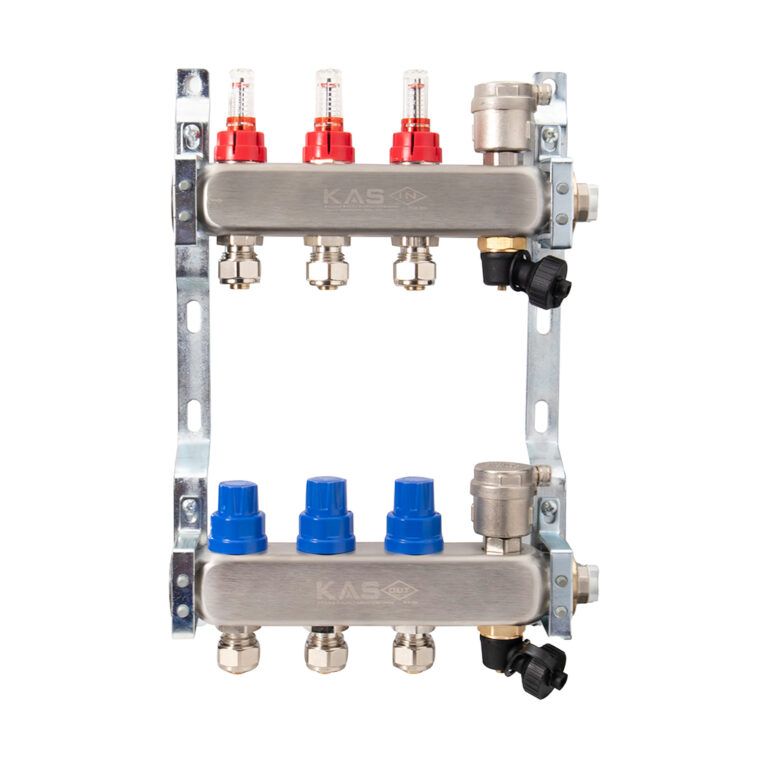
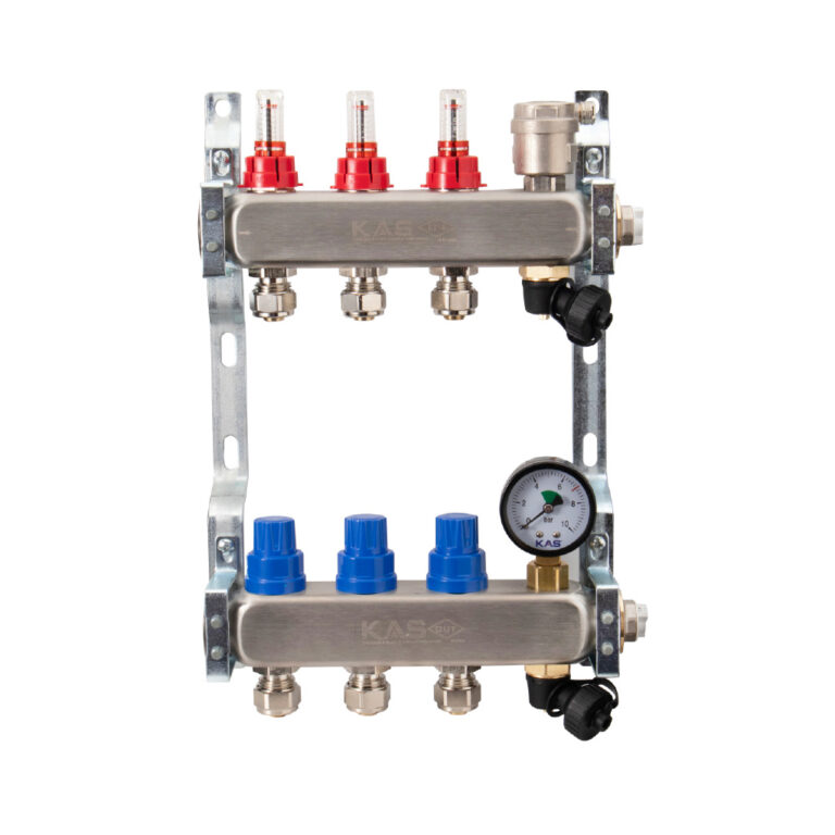
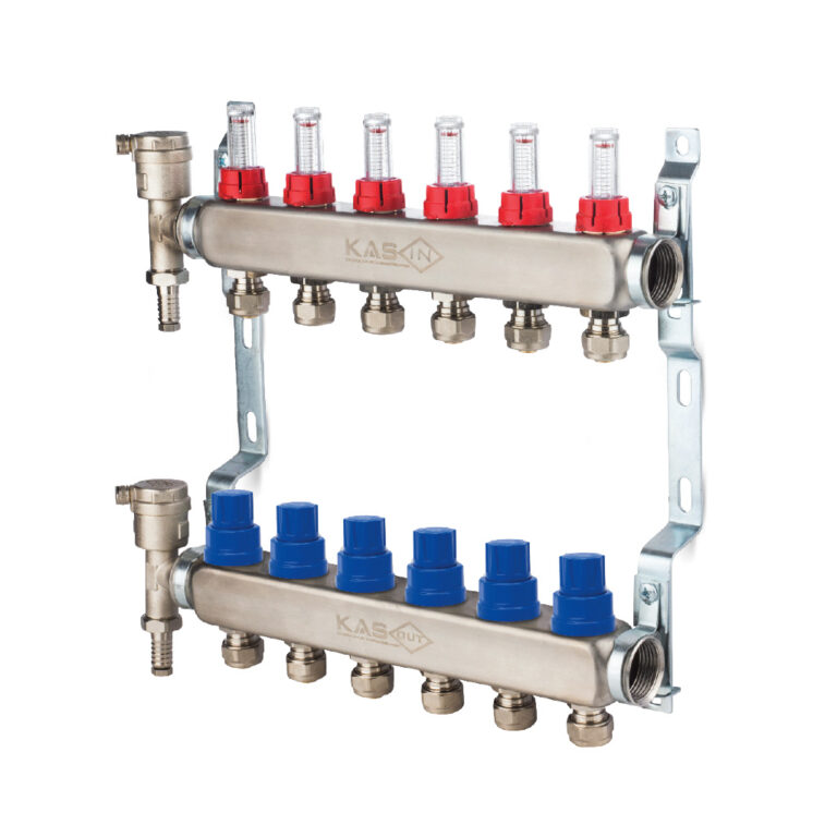
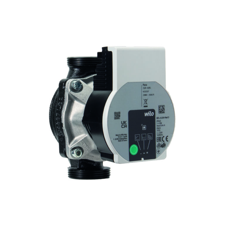
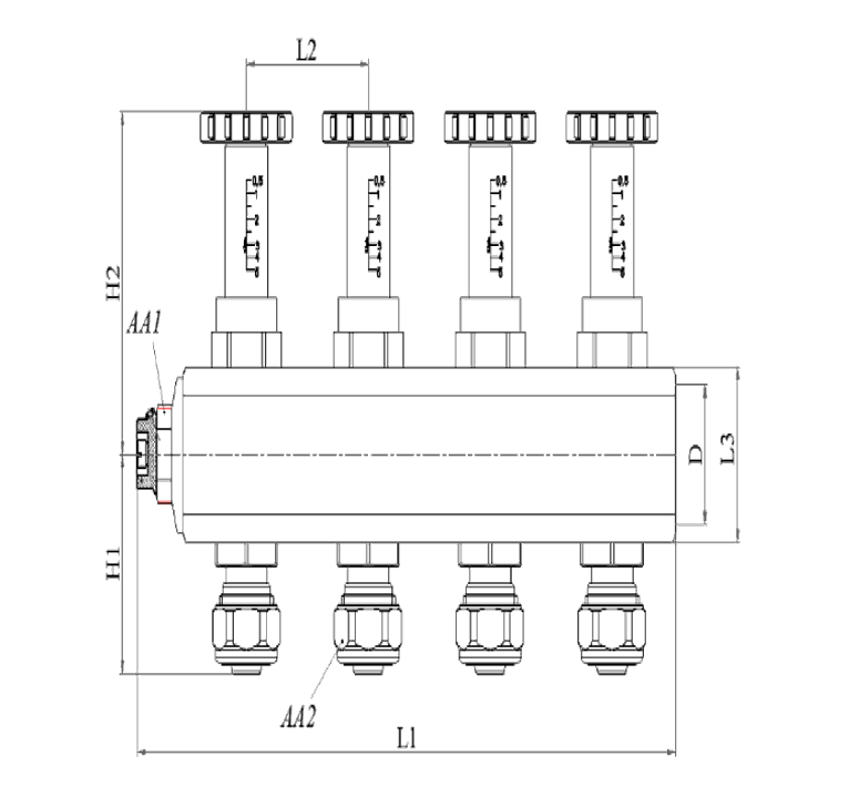
1″ Flow Meter Controlled Manifold (16X2)
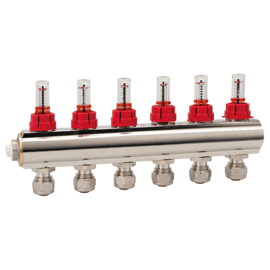
In hot/cold water installation systems, it ensures that the water coming from the feeder is distributed to other lines in the system or collected from other lines in the system.
Technical Data Sheet
| Product Name | 1″ Flow Meter Controlled Manifold (16X2) |
| Standard | TSE K |
| Max. Flow Temperature | 90°C |
| Pressure Class | PN 10 |
| Intended Use | Plumbing System |
Product Code (1801…
| DIM. | 502 | 503 | 504 | 505 | 506 | 507 | 508 | 509 | 510 | 511 | 512 | 513 |
|---|---|---|---|---|---|---|---|---|---|---|---|---|
| D | 1″ | 1″ | 1″ | 1″ | 1″ | 1″ | 1″ | 1″ | 1″ | 1″ | 1″ | 1″ |
| H1 | 50 | 50 | 50 | 50 | 50 | 50 | 50 | 50 | 50 | 50 | 50 | 50 |
| L1 | 114 | 161 | 208 | 255 | 302 | 349 | 396 | 443 | 490 | 537 | 584 | 631 |
| L2 | 47 | 47 | 47 | 47 | 47 | 47 | 47 | 47 | 47 | 47 | 47 | 47 |
| H2 | 79 | 79 | 79 | 79 | 79 | 79 | 79 | 79 | 79 | 79 | 79 | 79 |
| AA1 | 22 | 22 | 22 | 22 | 22 | 22 | 22 | 22 | 22 | 22 | 22 | 22 |
| L3 | 39 | 39 | 39 | 39 | 39 | 39 | 39 | 39 | 39 | 39 | 39 | 39 |
| AA2 | 24 | 24 | 24 | 24 | 24 | 24 | 24 | 24 | 24 | 24 | 24 | 24 |
Installation and Operating Instructions
- Make sure there is no damage on the product may occur during transport and shipping. Before assembly do not unpack the product in order to prevent from the external effects.
- Clean all kinds of contaminants before assembly.
- Make sure that the thread length to be connected to the valve is not too short or too long than the thread length of the valve.
- Keep the valve in closed position during installation. Install the valve with the appropriate tool from the side where you’ll mount it.
- Use enough flax or plumping adhesive.
- Use the valve full open or full closed
- While opening and closing the valve, follow the arrows on the handle.
- Do not paint the valve, do not expose the valve with abrasive chemicals.
- Do not open or close with any other tool and do not remove the handle.
