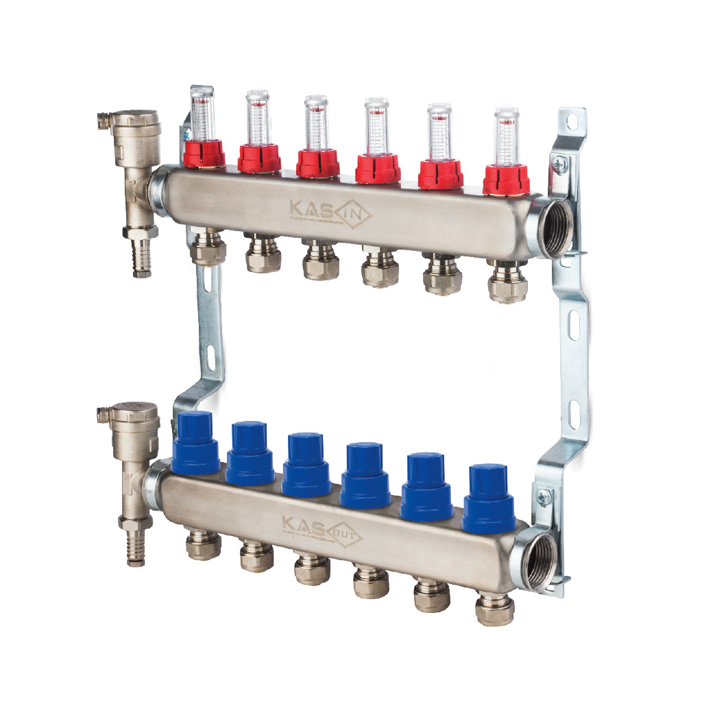
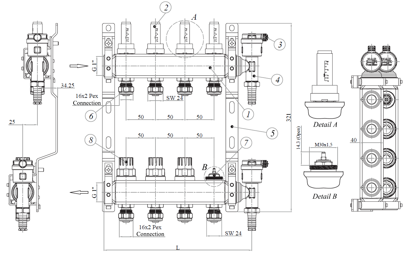
Installation and Operating Instructions
- Make sure there is no damage on the product may occur during transport and shipping. Before assembly do not unpack the product in order to prevent from the external effects.
- Clean all kinds of contaminants before assembly.
- Make sure that the thread length to be connected to the manifold is not too short or too long than the thread length of the manifold.
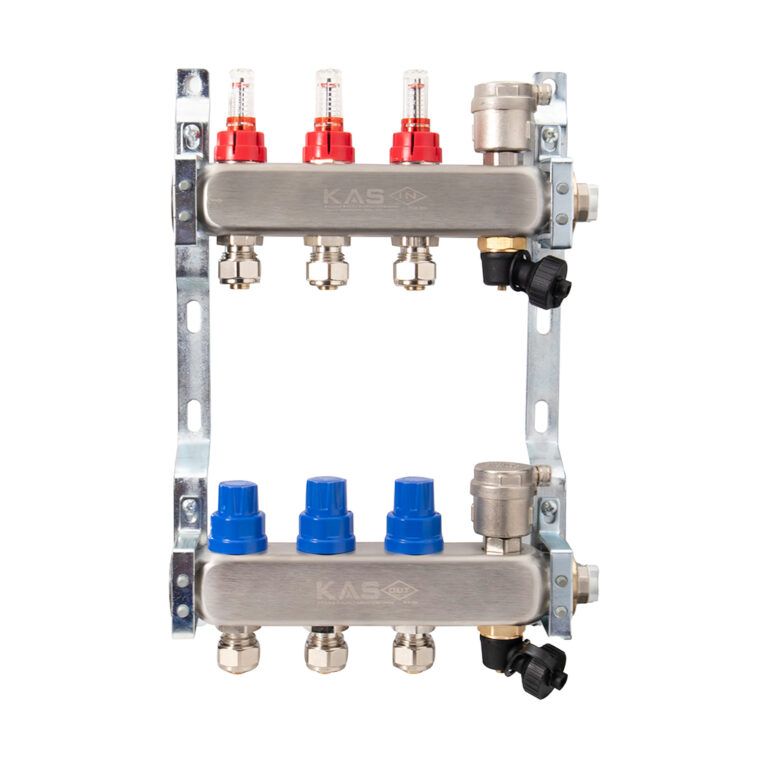
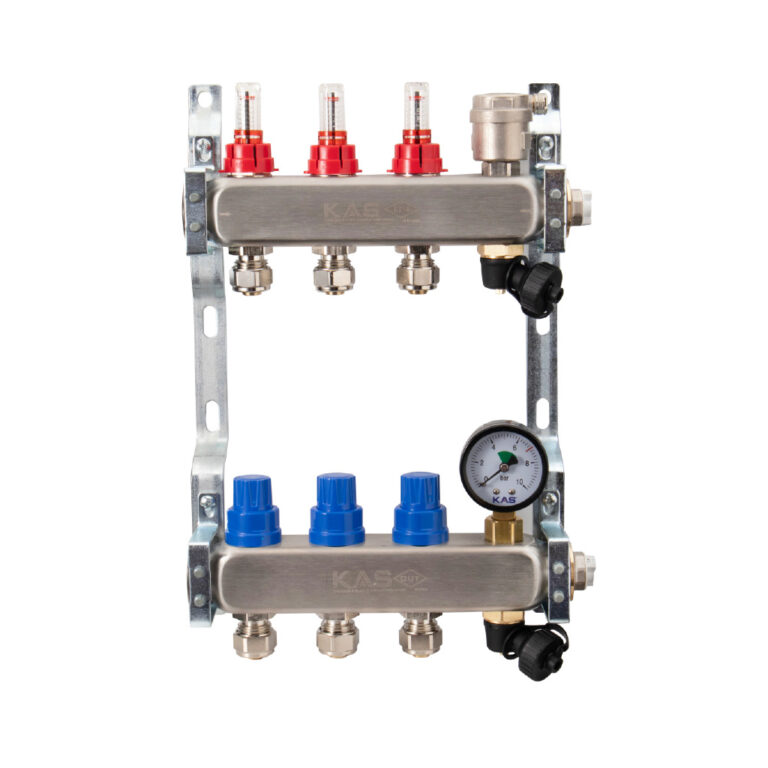
- Install the Manifold to the system by the appropriate tools.
- First, install the Nut,Ring and Socket to the hose, then screw the nut to the manifold by the appropriate tools.
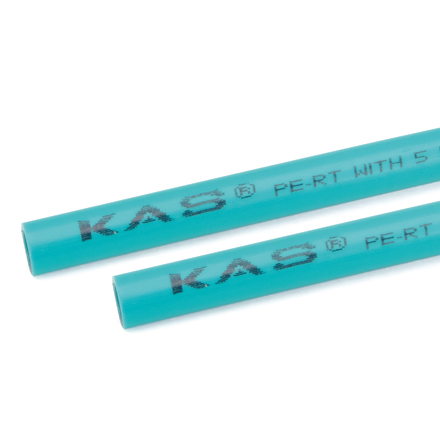
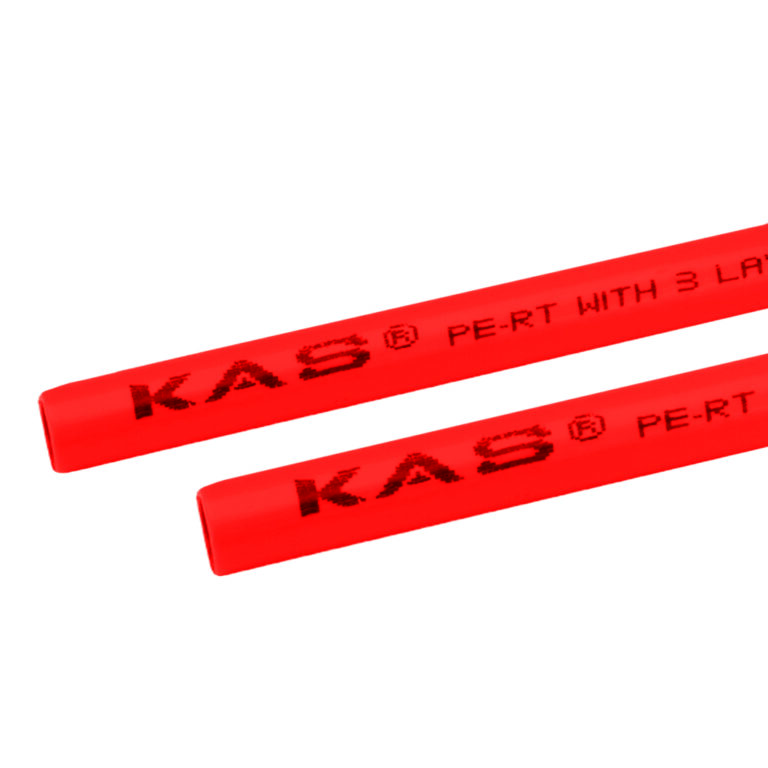
- Make sure the hose to be connected to the manifold is the correct size.
- Observe the axiality during assembly.
- The installation system that manifold connected must be protected against the freezing.
- Manifold is suitable for use in heating systems and should not be used in flammable or combustible gas / liquid installations.
- Do not paint the manifold, do not expose the manifold with abrasive chemicals, do not open or close with any other tool and do not remove the handle.
